
PIC10 Games Board
A production-ready PCB that turns the DIY PIC10F200 games from the microcontroller series into a compact custom board with USB-C power, on-board regulation, ICSP programming header, and traffic-light LEDs.
Board specs
- Input
- 5 V via USB-C or 2-pin barrel
- Output
- 3.3 V (on-board TPS79333 LDO)
- Dimensions
- 52.1 × 88.9 mm
- Layers
- 2 layers
- Fabricated by
- JLCPCB
- Quantity ordered
- 5
- Cost
- $0.90 ea (5-pcs + shipping = $4.49)
Overview
The PIC10 Games board is the physical destination for the PIC10F200 microcontroller series. Everything the tutorials build up on breadboard and perfboard — three LEDs, a debounced button, an in-circuit programming header, and on-board power regulation — is compressed onto a single 52 × 89 mm two-layer PCB.
The board accepts either 5 V USB-C or a keyed 2-pin header for a barrel connector. A TPS79333 LDO drops that down to the 3.3 V supply the PIC10F200 runs on. The programming pins are broken out to a 5-pin 0.1 in header laid out to match a PICkit-style ICSP cable.
Design intent
- Learn-microcontrollers destination: every part on this board is introduced somewhere in Series 1 through 5 of the blog. Nothing on the board is magic.
- Zero surface mount to hand-solder: except for the LDO, all parts are through-hole so a beginner can build it with a basic iron.
- Reprogrammable in-place: the 5-pin ICSP header exposes MCLR, VDD, GND, ICSPDAT, and ICSPCLK so you can flash new games without pulling the chip.
- Cheap to fabricate: five boards from JLCPCB shipped internationally for $4.49 — the cost of a coffee.
Manufacturing notes
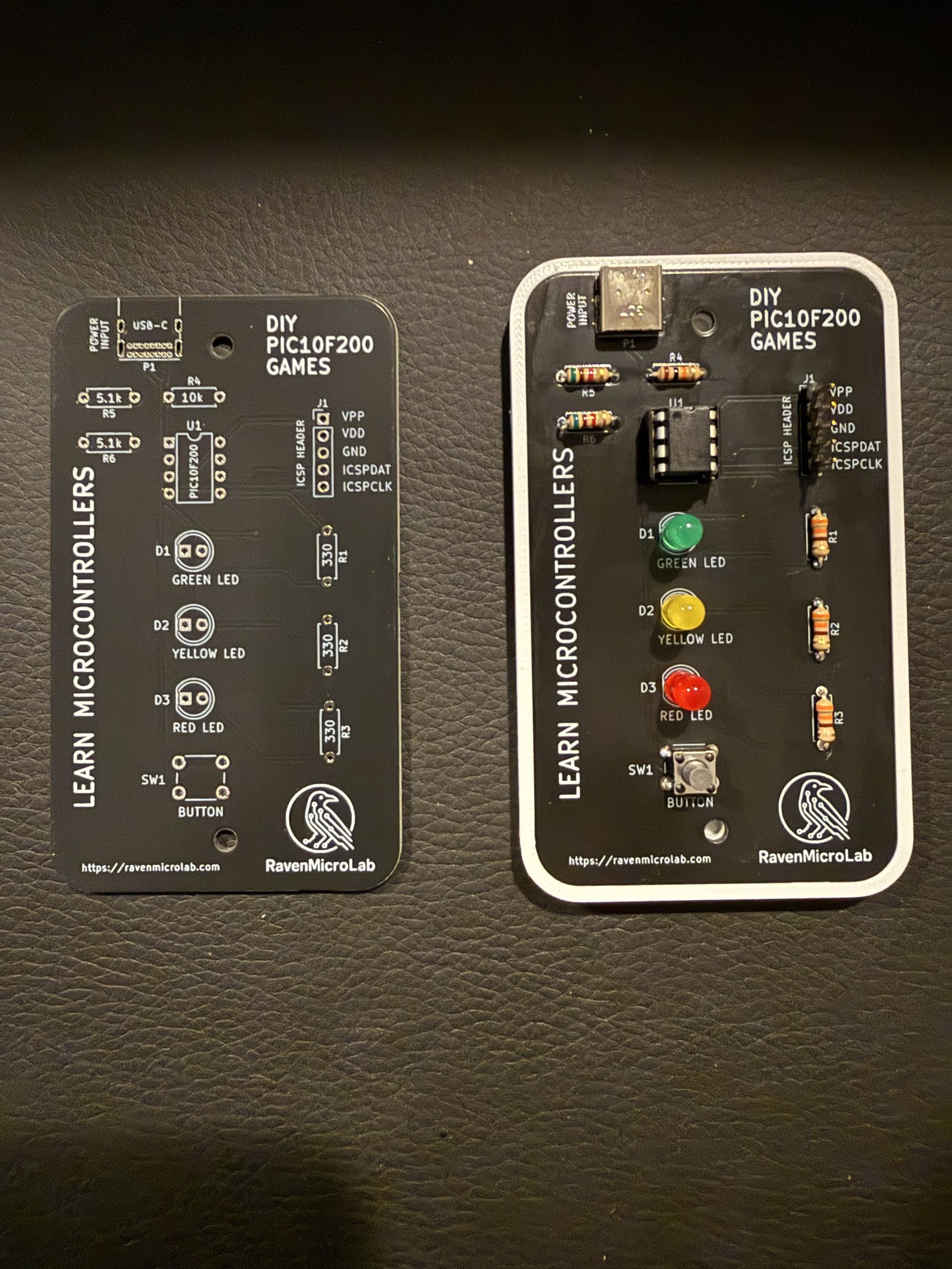
I sent the standard KiCad-generated Gerbers to JLCPCB with default 1.6 mm 2-layer black-soldermask/white-silkscreen settings. Turnaround was 3 days in fab plus about a week of shipping. The bare boards drop in below.
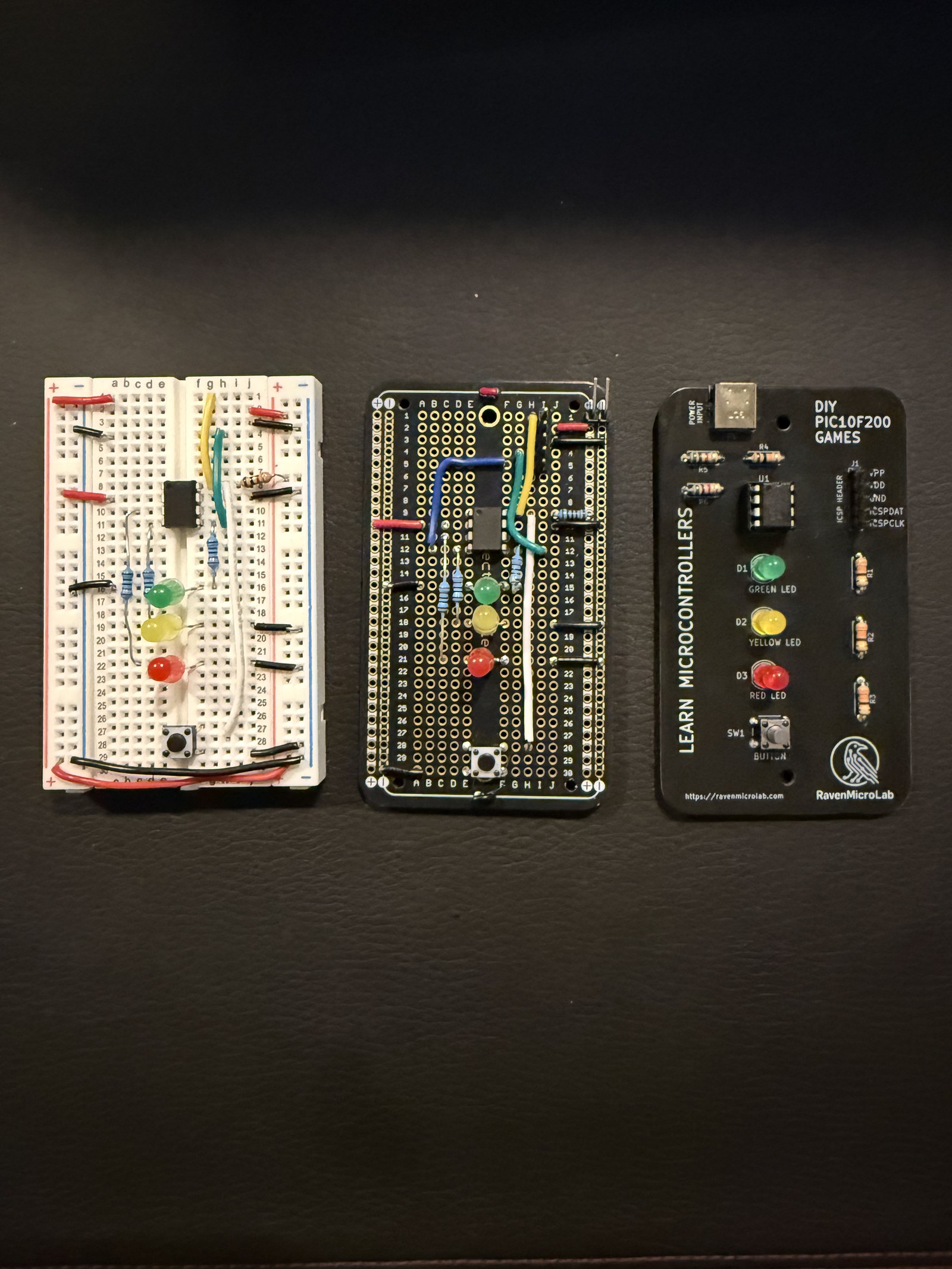
If you want to see the evolution from breadboard to perfboard to PCB, this shot from the assembly bench captures the whole arc:
Programming
The board is programmed with a PICkit 3, PICkit 4, or MPLAB SNAP over the 5-pin ICSP header (VPP, VDD, GND, ICSPDAT, ICSPCLK, silkscreen-labeled on the board). Any of the games from Series 5 can be flashed as-is — the pin assignments on the board match the tutorial code.
Bringing it up
- Power sanity check — with no PIC in the socket, apply 5 V and verify the LDO output pin sits at 3.3 V ±3%.
- Insert the PIC10F200 — orient pin 1 toward the ICSP header side.
- Flash the running-lights sketch first — this proves LED driver current is right before you fight with debounce.
- Add the button game last — Series 5 has the code and the debounce discussion.
What I would change next
- Move to the SOT-23-5 SMD version of the PIC10F200 to shrink the board further.
- Add a 32.768 kHz crystal footprint so the board can double as a sleep-mode demo.
- Break out one more GPIO to a 0.1 in pad for expansion (buzzer, second button, etc.).
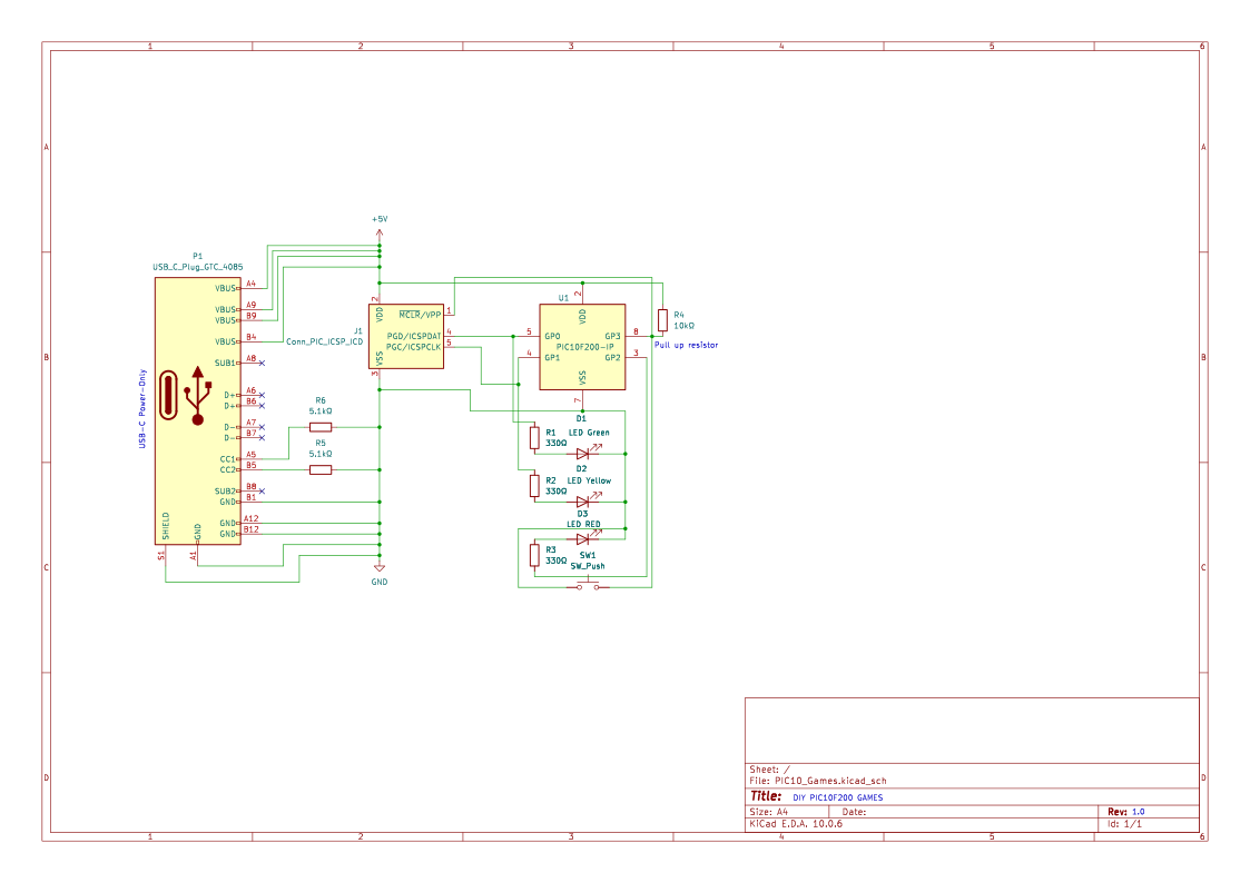
Schematic
Drag to pan · scroll to zoom
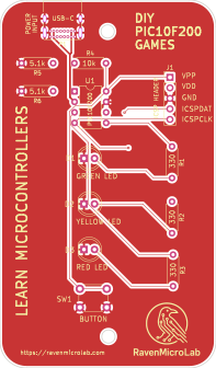
Top layer
Drag to pan · scroll to zoom
Downloads
Everything you need to fabricate or remix this board.